Contact
Dolni Roven 153, 53371 Dolni Roven
Czech republic
phone: +420 725 884 930
info(a)mipec.eu
TrackMaker - Tutorial
Introduction
This tutorial guides through process of working with TrackMaker. It will cover basic importing, aligning, tool path generation and milling procedure.
Importing files
Layer import
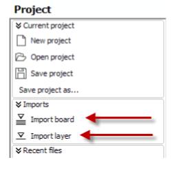
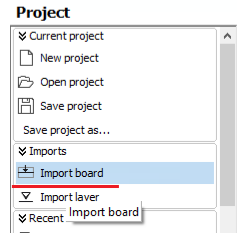
Go to Imports window and in this window click on Import layer. You can alternatively select Import board that will import all know layers. This however explains how to import data layer by layer.
Go to the folder where your data is stored and select layer to import. Note, that each layer of the board has different extension. For example, bottom layer may have extension .GBL or some other. In our case this is .BOT.
Your layer is now visible on the screen and in front of layer there is window, where layer parameters are displayed. Import to layer property should be set to Bottom layer
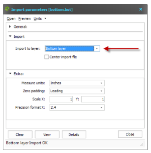
*If the layer isn’t correct, you can always change the layer by selection other value from the drop down list.
Close the window by clicking on Close button
Repeat this process for all other layers – top, drills and outline.
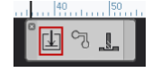
NOTE: If your layers have correct extensions, you can import all layers at the same time by click to button in pop-up window on the top side of screen.
Or by clicking to Import board command in Imports window
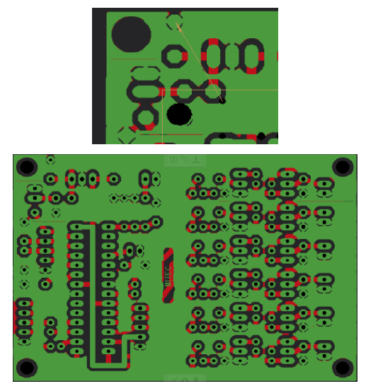
Layer alignment
Sometimes it can happen that drill layer is not perfectly aligned to bottom and top layer. This can happen when the Excellon file that is imported in TrackMaker comes from older CAD software or when the formatting in the file is not correct. However, importing and correcting this is very easy.
To align drills you have to do following:
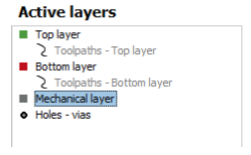
Choose the drill layer from Active layers window
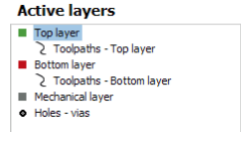
This makes current layer (holes in this case) active so elements can be selected and moved.
Choose Align layer to – Pad in right menu.
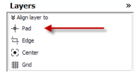
Now select the reference drilled hole (click the on the hole).
Click on the reference pad (place where the drill has to be positioned).
Drills are perfectly aligned with top and bottom layer now.
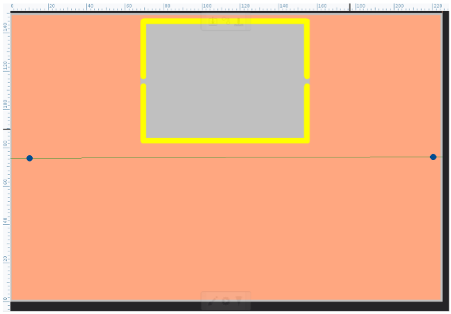
Creating Break-out tabs
Break-out tabs are small tabs (bridges) in board outline. These tabs hold the milled PCB attached to the rest of material during outline cutting, without the risk of breaking the tools or damaging already milled PCB.
To create Break-out tabs do the following:
Choose the Mechanical layer from Active layers window
In Create window in right menu click to Break-out bridges
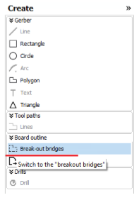
Click on board outline; Pop-up dialog will ask you to enter the width of the bridge. Usual values are between 0,5 and 2mm. Smaller value can cause unplanned breaks and bigger value can caused difficult breaking out.
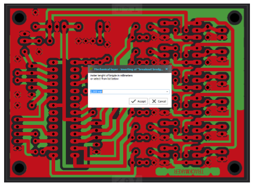
Click on Accept button and the break-out bridge with defined width is created.

Repeat the steps as above also on the opposite side of the PCB
It is recommended to have two bridges on opposite sides of the PCB. This way board is well fixed, but it is still easy to break it out.
If you want to delete the break-out bridge, simply click on it and bridge will be deleted.
Calculating the toolpaths
Contouring is the process of generating tool paths for PCB.
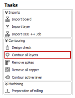
Choose Tasks command from the left menu and then choose Contour all layers
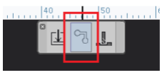
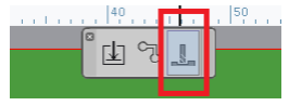
Alternatively you can use the quick button in the production toolbar.
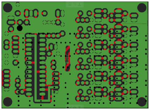
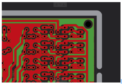
Tool paths for all layers are calculated and shown on the screen.
Milling the PCB
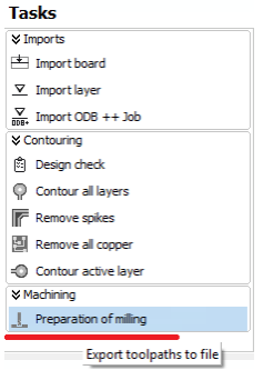
When all steps above are done, you can move the PCB artwork to the machining window by click on Preparation of milling command in Machining window on left menu.
Alternatively you can click Machining button in the Production toolbar.
Generated PCB is then moved to visual machine table.
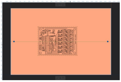
How to move the board on machine table?
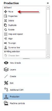
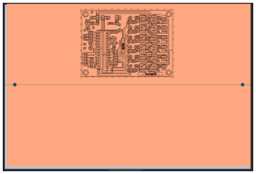
If you wish to move the PCB on place where it should be milled, click on Production in right menu and then click on Move command in Board window
Now move the cursor somewhere to the PCB, simply click mouse left button and move the cursor on the place where you want to mill the board.
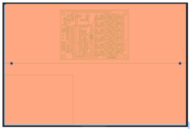
Click once more mouse left button and PCB is than placed on the required area.
Now you are almost ready to start the milling process. Make sure, that machine is connected by USB cable to computer and that the machine is supplied accordingly to the machine instructions.
Switch the machine on. If machine needs to do a reference run you will be prompted.

Simply click Yes and wait until the reference run is finished.
In the right menu click on Machine controls and then click to Parking position command in Move to window. Working table will then move to position where the underlay material and board can easily be placed. When the material is placed you are ready to start.
Starting the milling process
Please make sure that you have all required tools available. After clicking on start button, software will ask you to load the required tool.
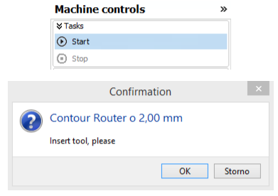
Insert the required tool and click OK button. Motor will start and machine will start moving and milling/drilling the board. When the operation is finished, if required, software will ask to load other tools until the complete process is finished.
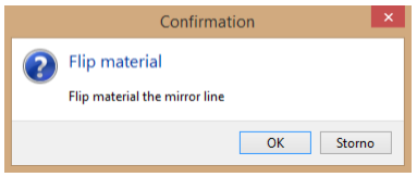
If it is required to mill a double-sided board, after the first side is fully made, software will ask to flip the material and then continue milling on the other side.
When milling process is finished, motor stop and machine will inform You by pop-up window that milling process is finished.
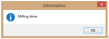
Click OK button. Your PCB is now completely milled.
Software will create the image of the cutout on the material for future reference. These cutouts can be deleted when not used or when the complete material is used up.